This manual details borehole design for MWe power plants, referencing the 2013 MWE Water Supply Design Manual, and focusing on seismic monitoring and deep reactor applications.
Purpose of the Manual
This manual serves as a comprehensive guide for engineers and technicians involved in the design, construction, and maintenance of boreholes specifically for MWe (Megawatt electric) power generation facilities. It consolidates best practices and regulatory requirements, particularly those outlined in the MWE Water Supply Design Manual of 2013.
The primary aim is to standardize borehole development for diverse applications, including conventional geothermal plants, deep fission gravity reactors (reaching one mile underground), and crucial seismic monitoring arrays – vital for safety and operational efficiency. It addresses optimal design for microearthquake monitoring in anisotropic media, as seen in projects like the Sabalan, Iran plant.
Scope and Applicability
This manual’s scope encompasses all phases of MWe borehole development, from initial geological and hydrogeological investigations to final borehole completion and rehabilitation. It’s applicable to a wide range of MWe power plant designs, including those utilizing recycled nuclear fuel with potential scaling up to 100 MWe, as explored by Oklo.
Specifically, it covers borehole design for seismic monitoring – including 3D array configurations – and the unique requirements of deep fission gravity reactors, demanding one-mile deep boreholes. The guidelines are relevant to projects globally, referencing standards and regulations, and aiding in compliance.
Target Audience
This manual is primarily intended for engineers and geoscientists involved in the planning, design, and implementation of MWe borehole projects. This includes drilling contractors, hydrogeologists assessing aquifer properties, and specialists in borehole seismic array design for microearthquake monitoring, particularly within the context of geothermal or nuclear power plants like those planned for Sabalan, Iran.
Additionally, it serves as a valuable resource for regulatory bodies ensuring compliance with the MWE Water Supply Design Manual 2013, and project managers overseeing borehole construction and rehabilitation efforts.

Geological and Hydrogeological Investigations
Thorough site characterization, aquifer assessment, and geological logging are crucial for successful MWe borehole design, informing optimal placement and construction techniques.
Site Characterization
Comprehensive site characterization is the foundational step in MWe borehole design, demanding detailed analysis of the subsurface environment. This involves gathering existing geological data, conducting geophysical surveys – like seismic reflection and resistivity imaging – and initiating preliminary borehole investigations.
Crucially, the Uganda Borehole Information Portal highlights the importance of capturing data from borehole completion reports. Analyzing regional geological maps, identifying potential fault zones, and assessing the overall structural geology are paramount.
Understanding the local hydrogeological framework, including groundwater flow patterns and recharge areas, is also essential for predicting borehole performance and ensuring sustainable water supply for power plant operations.
Aquifer Properties Assessment
Accurate assessment of aquifer properties is vital for optimizing MWe borehole performance and long-term sustainability. This necessitates determining key parameters such as hydraulic conductivity, transmissivity, storativity, and effective porosity. Standard techniques include conducting pumping tests, analyzing borehole logs, and performing grain size analysis on core samples.
Data from the Uganda Borehole Information Portal, derived from completion reports, contributes to regional aquifer characterization.
Careful interpretation of these parameters allows for predicting borehole yield, drawdown, and the overall efficiency of water extraction for the MWe power plant’s cooling or operational needs.
Geological Logging and Borehole Core Analysis
Detailed geological logging during drilling is crucial for understanding subsurface conditions and informing borehole design. This involves meticulously documenting lithology, stratigraphy, fracture patterns, and groundwater levels. Borehole core analysis provides invaluable physical data, including rock type, density, porosity, and permeability.
These analyses, alongside data captured in borehole completion reports (like those in the Uganda Borehole Information Portal), help identify potential drilling hazards and optimize casing/screen placement.
Accurate logging and core analysis minimize risks and ensure borehole stability for MWe power plant operations.
Borehole Design Considerations
Optimal borehole parameters—diameter, depth, casing, and screen design—are vital, guided by geological data and the 2013 MWE Water Supply Design Manual’s standards.
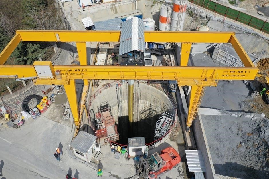
Borehole Diameter and Depth
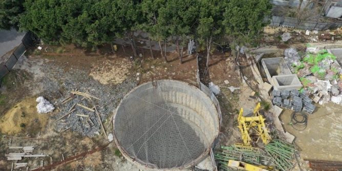
Determining appropriate borehole diameter and depth is crucial for MWe applications, heavily influenced by reactor capacity and geological formations. Deep Fission Gravity Reactors necessitate a significant depth—one mile underground—to ensure operational safety and efficient heat dissipation. Reactor footprint considerations dictate that each reactor, generating 15 MWe, requires a relatively compact borehole.
Scaling power output to 150 MWe involves deploying multiple reactors, demanding careful spatial planning of borehole locations. The 2013 MWE Water Supply Design Manual provides guidance, though specific dimensions are reactor-dependent. Depth impacts coolant velocity, a critical parameter for maintaining maximum permissible values within telescopic borehole designs.
Casing Material Selection
Casing material selection is paramount for MWe borehole integrity and longevity, particularly given the extreme conditions of deep fission reactors. The 2013 MWE Water Supply Design Manual outlines compliance requirements, stipulating specific metal casing specifications if utilized. These specifications address corrosion resistance, structural strength at depth, and compatibility with surrounding geological formations.
Material choices must withstand high pressures and temperatures, alongside potential seismic activity, especially crucial for microearthquake monitoring arrays in locations like Sabalan, Iran. Careful consideration prevents borehole collapse and maintains coolant containment, vital for reactor efficiency and environmental protection.
Screen Design and Placement
Effective screen design and strategic placement are critical for maximizing water inflow in MWe boreholes, particularly for geothermal or water supply applications referenced in the MWE Water Supply Design Manual. Screen slot size must be carefully calculated based on aquifer properties assessment and geological logging data to prevent sand pumping.
Optimal placement considers aquifer thickness and permeability, ensuring efficient water extraction without excessive drawdown. For deep fission reactors, screens may be less relevant, but filtration systems are vital to prevent debris from impacting reactor performance and maintaining coolant integrity.
Drilling Techniques for MWe Boreholes
MWe borehole drilling employs rotary and percussion methods, demanding precise borehole deviation control, especially for deep reactor installations exceeding one mile in depth.
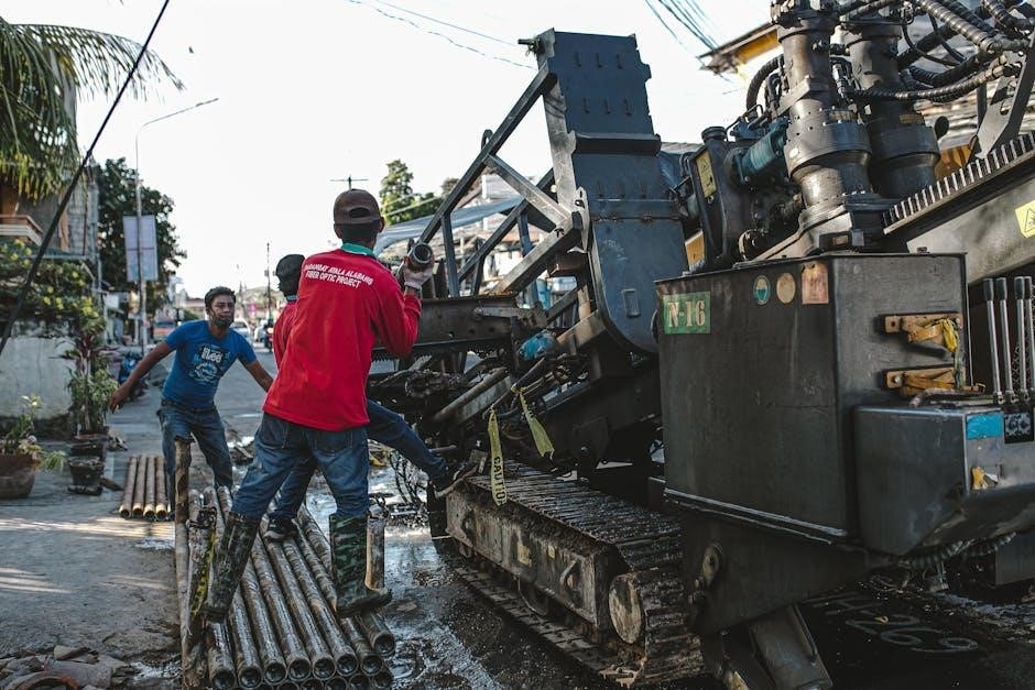
Rotary Drilling Methods
Rotary drilling is a cornerstone technique for MWe borehole construction, utilizing a rotating drill string to excavate the borehole. This method proves particularly effective when penetrating diverse geological formations encountered during site characterization for power plant locations, like Sabalan, Iran.
The process involves circulating drilling fluid – often a bentonite clay mixture – to remove cuttings, stabilize the borehole walls, and cool the drill bit. Careful monitoring of drilling parameters, including rotation speed and fluid pressure, is crucial to prevent borehole collapse and ensure efficient penetration. Telescopic boreholes, requiring precise control, benefit significantly from optimized rotary drilling procedures.
Furthermore, the selection of appropriate drill bits, tailored to the specific rock types, is paramount for maximizing drilling efficiency and minimizing downtime. This technique is foundational for achieving the necessary depth, exceeding one mile, for Deep Fission Gravity Reactor installations.
Percussion Drilling Methods
Percussion drilling, while less common than rotary methods for deep MWe boreholes, offers advantages in specific geological conditions. This technique relies on the repeated impact of a heavy drill bit to fracture and penetrate the subsurface. It’s particularly useful in formations where rotary drilling struggles, such as highly fractured or unconsolidated materials.
Down-the-hole (DTH) hammers are frequently employed, delivering concentrated impact energy directly at the bit face. Air or foam is circulated to remove cuttings. However, borehole deviation control can be more challenging with percussion drilling, necessitating careful monitoring and steering adjustments.
For shallower boreholes associated with seismic monitoring arrays, or initial site investigations, percussion drilling provides a cost-effective and efficient solution, complementing the deeper penetrative capabilities of rotary techniques.
Borehole Deviation Control
Maintaining accurate borehole trajectory is crucial for MWe borehole design, especially for deep fission reactor installations and 3D seismic arrays. Deviation from the planned path impacts reactor placement, monitoring accuracy, and overall project efficiency. Real-time directional drilling tools, including gyroscopic surveys and measurement-while-drilling (MWD) systems, are essential.
These tools provide continuous data on borehole inclination and azimuth, allowing drillers to make immediate corrections. Whipstocks and bent sub assemblies are utilized to steer the drill bit. Careful planning, considering geological formations and stress regimes, minimizes unwanted deviation.
Regular deviation surveys and adherence to strict quality control protocols are paramount throughout the drilling process.
Borehole Development and Testing
Effective well development and rigorous testing are vital, including pumping tests and water quality analysis, to ensure optimal performance for MWe power plant applications.
Well Development Procedures
Thorough well development is crucial for maximizing borehole yield and ensuring long-term operational efficiency. This process involves removing drilling fluids, fines, and any other materials that impede water flow. Techniques include surging, backwashing, and jetting, carefully applied to avoid damaging the formation. Development continues until water turbidity reaches acceptable levels, indicating a stable aquifer.
Specific procedures must align with the geological context and borehole characteristics, as outlined in the MWE Water Supply Design Manual 2013. Proper development minimizes well losses and optimizes hydraulic connectivity, ultimately enhancing the performance of MWe power plant water supply systems and related geothermal applications.
Pumping Test Analysis
Pumping tests are essential for characterizing aquifer performance and validating borehole design. Data collected during these tests – drawdown, recovery rates – are analyzed using established methods like the Theis equation to determine transmissivity and storativity. Accurate analysis, guided by the MWE Water Supply Design Manual 2013, is vital for sustainable water resource management.
Results inform optimal pumping rates and well yields, preventing over-extraction and ensuring long-term supply for MWe power plant operations. Careful interpretation also identifies potential well interference and assesses the aquifer’s capacity to meet projected demands, crucial for reliable energy production.
Water Quality Analysis
Comprehensive water quality analysis is paramount throughout the MWe borehole lifecycle, as outlined in the MWE Water Supply Design Manual 2013. Initial baseline assessments establish pre-development conditions, while regular monitoring tracks changes post-development. Parameters analyzed include pH, conductivity, dissolved solids, and potential contaminants, ensuring compliance with regulatory standards.
Detailed analysis informs appropriate treatment strategies, protecting equipment from scaling or corrosion, and safeguarding public health. Data guides disinfection procedures and ensures the water source consistently meets the stringent requirements of MWe power plant operations, guaranteeing efficient and reliable energy production.

Seismic Monitoring Borehole Design (Related to MWe Power Plants)
Borehole designs support 3D seismic arrays for microearthquake monitoring, crucial for MWe plant safety in regions like Sabalan, Iran, as detailed in research.
3D Borehole Seismic Array Design
Optimizing 3D borehole seismic array design is paramount for accurate microearthquake monitoring, particularly near MWe power plants. Effective array geometry, considering borehole spacing and depth, enhances resolution and data quality. Research, such as that conducted for the EGS collaboration project, emphasizes designs tailored for anisotropic media, improving waveform imaging. These arrays are vital for detecting and locating induced seismicity during stimulation processes. Careful consideration must be given to receiver coupling and noise mitigation strategies. The goal is to create a robust network capable of characterizing subsurface fracture networks and assessing potential seismic hazards associated with geothermal or deep fission reactor operations.
Anisotropic Media Considerations
Accurate seismic wave velocity modeling is crucial when designing borehole arrays in anisotropic media, common in geothermal and fractured rock formations. Ignoring anisotropy can lead to mislocated events and inaccurate reservoir characterization. The MWe borehole design must account for variations in seismic velocity with direction, utilizing techniques like shear-wave splitting analysis. Research highlights the importance of anisotropic corrections during data processing, particularly for microearthquake monitoring in the Sabalan region of Iran. Proper consideration of anisotropy improves the reliability of seismic imaging and hazard assessment for MWe power plant operations.
Microearthquake Monitoring Applications
Borehole seismic arrays are vital for monitoring microearthquakes induced by Enhanced Geothermal Systems (EGS) and deep fission reactors associated with MWe power plants. These arrays, designed per the MWe borehole design manual, provide high-resolution data for locating events and characterizing subsurface fracture networks. Applications include assessing reservoir stimulation effectiveness and detecting potential seismic hazards. Optimal 3D array designs, as researched for the EGS collaboration project, enhance monitoring capabilities. Accurate location is critical for safe and efficient MWe power generation, requiring careful borehole placement and sensor calibration.
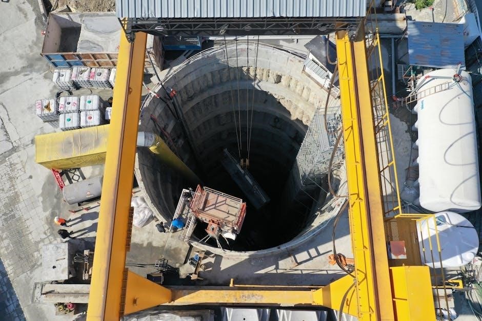
Borehole Completion and Rehabilitation
Completion involves gravel packing, disinfection, and security measures, as outlined in the MWe borehole design manual, ensuring long-term functionality and protecting water resources.
Gravel Packing and Filtration
Gravel packing is a crucial step in borehole completion, stabilizing the wellbore and preventing sand production. The MWe borehole design manual emphasizes selecting appropriate gravel size based on aquifer characteristics and screen slot dimensions. This process enhances filtration, minimizing turbidity and maximizing well yield.
Effective gravel pack design considers gravel uniformity, placement techniques, and compatibility with casing materials. Proper filtration extends the borehole’s operational lifespan, reducing maintenance frequency and ensuring consistent water quality. The manual details specifications for gravel materials, advocating for rounded shapes to minimize bridging and maximize permeability. Careful execution of gravel packing is paramount for sustainable MWe power plant water supply.
Disinfection Procedures
The MWe borehole design manual prioritizes water quality, outlining rigorous disinfection procedures post-completion and for routine maintenance. Initial disinfection typically involves chlorine shock treatment, eliminating bacterial contamination introduced during drilling and development. Specific chlorine dosage is determined by borehole volume and water chemistry analysis.
The manual details protocols for monitoring residual chlorine levels, ensuring effective disinfection without exceeding safe limits. Alternative disinfection methods, like ozone or UV irradiation, are also considered. Regular disinfection schedules are crucial for maintaining potable water standards, safeguarding public health, and preventing biofouling within the borehole system, ensuring reliable MWe power plant operation.
Borehole Security and Protection
The MWe borehole design manual emphasizes robust security measures to protect vital water resources and infrastructure. This includes secure wellhead construction, utilizing tamper-proof casings and locking mechanisms to prevent unauthorized access or vandalism. Perimeter fencing and surveillance systems are recommended, particularly for boreholes supporting critical MWe power plant operations.
The manual also addresses protection against contamination, detailing procedures for sealing abandoned boreholes and implementing buffer zones around active sites. Regular inspections and maintenance are vital for identifying and addressing potential security vulnerabilities, ensuring the long-term integrity and reliable operation of the MWe water supply system.

Design Standards and Regulations (MWE Water Supply Design Manual 2013)
The 2013 MWE manual dictates compliance requirements, including metal casing specifications and hydrological design aids, ensuring safe and effective borehole construction practices.
Compliance Requirements
Adherence to the MWE Water Supply Design Manual 2013 is paramount for all borehole projects associated with MWe power generation. This includes stringent protocols for site characterization, geological logging, and aquifer property assessments. Specifically, any metal casing utilized must meet the detailed specifications outlined within the manual, ensuring structural integrity and preventing contamination. Furthermore, designs must incorporate appropriate hydrological design aids to guarantee sustainable water resource management.
Stakeholder agreement – involving districts, MWE/DWD, and others – is crucial for alternative approaches. Documentation of all borehole completion reports is essential for data capture and regulatory oversight, maintaining transparency and accountability throughout the project lifecycle.
Metal Casing Specifications
The MWE Water Supply Design Manual 2013 dictates precise metal casing requirements for borehole integrity. Specifications cover material grade, wall thickness, and corrosion resistance, crucial for long-term performance and preventing groundwater contamination. Casing must withstand anticipated borehole pressures and external loads, ensuring structural stability throughout the operational lifespan of the MWe facility.
Detailed standards address joint types, welding procedures, and protective coatings. Compliance verification involves rigorous material testing and inspection during installation. Proper casing selection is vital for maintaining borehole functionality and adhering to environmental regulations, safeguarding water resources and operational safety.
Hydrological Design Aids
The MWE Water Supply Design Manual 2013 incorporates essential hydrological design aids to optimize borehole performance and water resource management. These aids facilitate accurate estimations of groundwater availability, recharge rates, and sustainable yield. Uganda’s Borehole Information Portal exemplifies data capture from completion reports, aiding informed decision-making.
Design considerations include aquifer characteristics, pumping rates, and water quality parameters. Utilizing these aids ensures efficient water extraction while minimizing environmental impact. Proper hydrological assessment is crucial for long-term borehole sustainability and reliable water supply for MWe power plant operations.
Deep Fission Gravity Reactor Boreholes
These boreholes, one mile underground, house Deep Fission Gravity Reactors, each generating 15 MWe, with ten reactors scaling output to 150 MWe.
Borehole Location and Depth (1 Mile Underground)
Strategic borehole placement is crucial for Deep Fission Gravity Reactors, requiring a depth of one mile underground to ensure containment and optimal operational conditions. This substantial depth provides significant shielding from external influences and enhances safety protocols. Careful geological assessments are paramount to identify stable rock formations capable of supporting the reactor infrastructure. The location must also consider thermal dissipation characteristics of the surrounding geology. Precise drilling and casing procedures are essential to maintain borehole integrity at these extreme depths, preventing any potential leakage or instability. Thorough site characterization, including seismic activity analysis, is integral to the borehole location selection process.
Reactor Capacity and Footprint (15 MWe per Reactor)
Each Deep Fission Gravity Reactor is engineered to generate 15 MWe of power, representing a compact and efficient energy source. This design prioritizes a small physical footprint, minimizing environmental impact and facilitating deployment in diverse geological settings. The concentrated power output allows for a higher energy density compared to conventional power generation methods. Multiple reactors can be strategically deployed within a single borehole complex to achieve larger-scale power generation, scaling up to 150 MWe with ten reactors. This modular approach offers flexibility and redundancy in power supply.
Power Output Scaling (Up to 150 MWe)
The modular design of the Deep Fission Gravity Reactor system enables scalable power output, reaching up to 150 MWe. This is achieved by deploying multiple reactors – up to ten – within a single, strategically designed borehole complex. This approach provides a flexible solution to meet varying energy demands, offering both redundancy and increased capacity. Scaling allows for phased implementation, minimizing initial investment and risk. The system’s inherent density allows for substantial power generation within a limited geological area, optimizing land use and reducing infrastructure requirements.